Shown below are mechanical schematics of the pivoting crank arm.
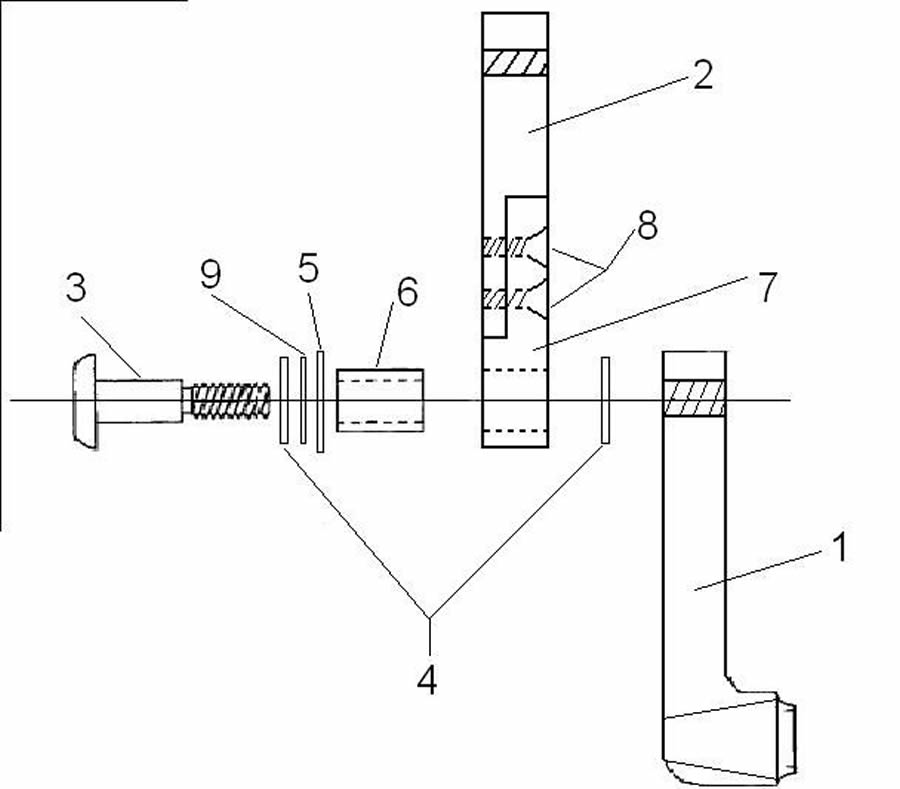
Figure B-1: See chart below for the corresponding part labels. This diagram shows the disassembled pivoting crank arm. From left to right, the shoulder screw passes through a thrust bearing, a metal washer, a Teflon washer, and a needle bearing before entering into the aluminum bar fastener. The shoulder screw then passes through another thrust bearing before threading into the inner crank arm section. (Click image for larger view)
1 |
Inside Crank Arm |
127 mm long |
2 |
Outside Crank Arm |
78 mm long |
3 |
Shoulder Screw |
5/8” diameter |
4 |
Thrust Bearing |
|
5 |
Teflon Washers |
|
6 |
Needle Bearing |
|
7 |
Aluminum Bar Fastener |
|
8 |
Fixation Screws |
¼”-20 |
9 |
Metal Washer |
|
Table B-1: Part Labels.
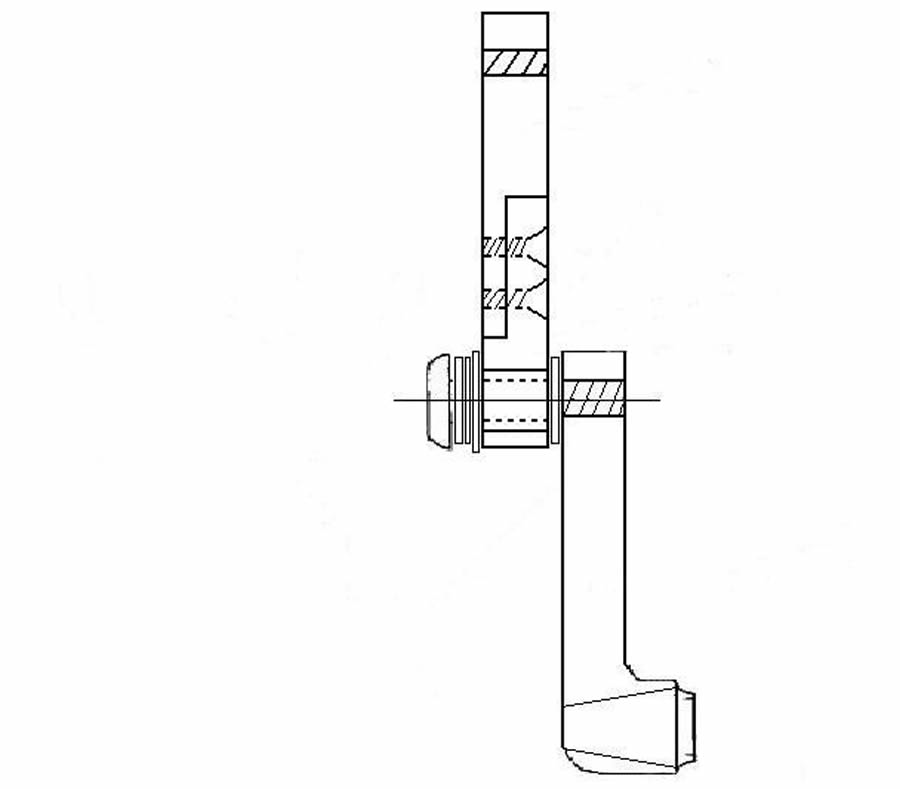
Figure B-2: This figure shows the assembled version of the pivoting crank arm, including the shoulder screw, all washers, all bearings, the aluminum bar fastener, and the crank arm sections. Note that the needle bearing is embedded inside the aluminum bar fastener. (Click image for larger view)